Headset: FOHMD
Manufacturer: CAE-Electronics Ltd
Cost: $250,000 (£183,078)
Launch Date: April 1992
Video in: NTSC or RGB
Imaging: Fiber optics, color light valves, color CRT
Resolution: 1,000 X 1,000
Weight: 5.0-6.0 lbs
Field of view: Up to 127HX66V, Pancake Window optics
Estimated Value: £20,000 – £50,000
Other Features: Top-of-the-line HMD. High resolution and wide field of view with higher resolution inserted at centre of view.
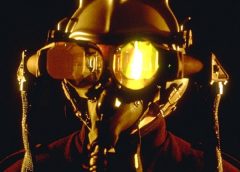
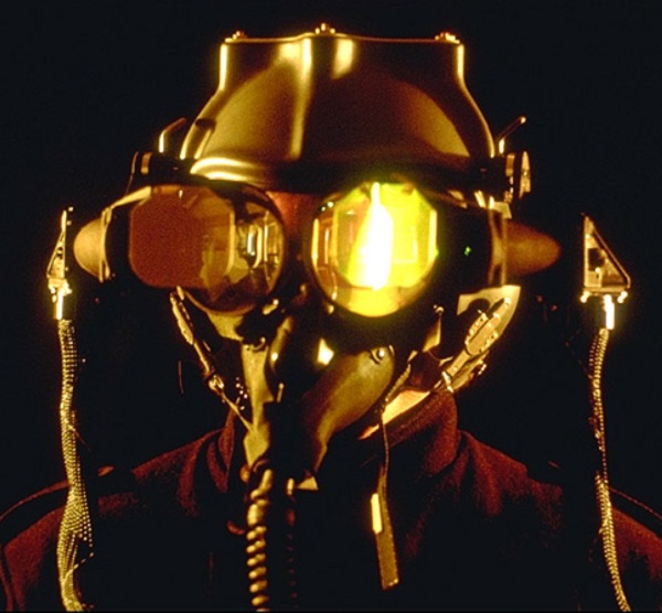
Made by Douglas Ball for Canadian Aviation Electronics it was designed for simulator use only. It used 4,000,000-element fibre-optic bundles and four overhead sensors that were directed at 6 helmet-mounted LEDs to determine head position and orientation. The system employs eye tracking and a collimated fibre optic bundle to carry an image to a set of mirrors, which then reflect the image into the eye. The image source can be anything that will connect to the feed end of the fibre optic bundle: a CRT, a slide projector, a microscope, or whatever image generator is appropriate.
The alignment of the two displays was critical and highly dependent upon a proper helmet fit. Some of the critical requirements that had to be met were that the helmet shell would be lightweight, but at the same time extremely rigid to be able to support the loads of the optic mounts.
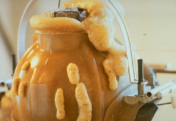
They managed to counteract the weight by moulding the HMD with a ‘foaming rig’, shown above which was developed to ensure the precise positioning of the mould to the pilots head. Polyurethane foaming agents were then poured into the moulds and instantaneously set to the shape of the head.
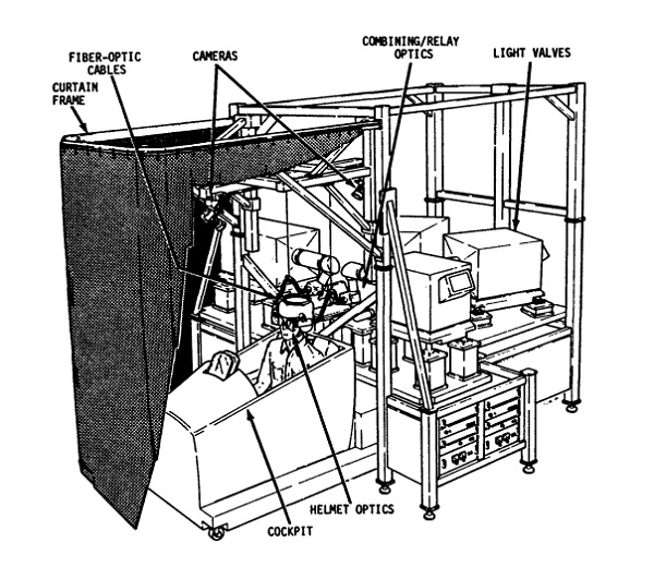
It was used in a static positional simulator as the diagram above shows. The primary goal for the FOHMD project was to provide a display device to supplement the DART display system. The research focused on two basic eyepiece designs. Both designs consisted of a semitransparent spherical mirror and a flat combining surface mounted at roughly a 45° angle to the optical axis of the spherical mirror. The fundamental difference between the two systems was that one system has the combiner and spherical mirror separated by an air space while the other system utilizes a combiner immersed in glass or plastic. This combiner is normally identified by the misnomer, “cube beamsplitter.” In this report, the air beamsplitter eyepiece will be referred to as an air combiner or air combining eyepiece, while the cube beamsplitter will be referred to as a prism combiner or prism combining eyepiece.
The major advantage of the prism combiner was that it effectively allowed the lengthening of the optical path, permitting the spherical mirror to be placed in a horizontal position (vertical optical axis) for the vertical fold configuration. This resulted in the eyepiece having only a single partially reflecting surface (the flat combining surface) to degrade the see-through transmission of the display. The DART imagery is not viewed through the spherical mirror and this made the simulation (while still basic) a little more believable.